Calculation of power for current and voltage
As you know, electrical voltage should have its own measure, which initially corresponds to the value that ...
Before commissioning an electrical installation or electrical equipment, it is necessary to conduct control tests of electrical installations, which allow to identify possible defects. In addition to the detection of defects during the verification of control tests, it is possible to obtain data that is necessary for conducting preventive inspections and for verifying the conformity of an installation or equipment with its technical characteristics and standards specified in technical regulations approved at the legislative level. To carry out control tests of electrical installations should be experts of electrical measuring laboratory, which has a certificate of registration in Rostekhnadzor.
Our company has repeatedly conducted control tests of electrical installations and has accurate measuring equipment and uses modern techniques in its work. This allows our specialists to conduct control tests of electrical installations with high quality and quickly. When our electrical measuring laboratory detects faults and defects, we help control the process and the quality of their elimination.
There are certain requirements when conducting control tests. These requirements are spelled out in EMP and ПТЭЭП. Among the requirements, it is worthwhile to talk about the established periods of such tests, since there is an obligation of organizations to conduct control tests of all existing electrical equipment at certain intervals. For example, electricity networks located in especially dangerous premises are carried out at least once a year. Other cases involve such tests 1 time in 3 years. Lift equipment and cranes are subject to inspection annually. Electric stoves are subjected to control tests only in a heated state and at least once a year. For other electrical installations and electrical equipment, the control tests are carried out in the terms established by the technical manager of the Consumer. depend on the type of equipment being examined.
The safety and reliability of electrical installations and equipment depends not only on compliance with technical requirements and standards, but also on regular inspections. Due to the existence of stringent requirements that impose supervisory authority, ensures the most secure operation of the object. To ensure the protection of people from electric shock, the safety of the equipment itself and to ensure fire safety, the facility itself should also regularly carry out control tests of the insulating materials of current-carrying elements and equipment components.
Page 3 of 19
During installation and after its completion, as well as under operating conditions, electrical equipment of electrical installations is tested, tested and adjusted.
Electrical equipment may be damaged during transport and installation. Damage due to normal wear and structural defects is possible during operation.
To set up electrical equipment have regulated requirements, for compliance with which conduct the following tests:
model in accordance with current Standards;
acceptance certificates in accordance with the EMP, and in some cases with the instructions of the Ministry of Energy;
preventive and others in accordance with the Rules for the Technical Operation of Power Plants and Networks (PTE), the volume and standards of electrical equipment tests and instructions for individual items of electrical equipment.
Type tests are carried out at the manufacturers according to the programs and with the volumes specified in the standards and technical conditions, but in part they can be carried out at the installation site of electrical installations. With type tests, the compliance of electrical equipment with the requirements set by standards is verified.
Acceptance tests are carried out in newly constructed and reconstructed installations up to 500 kV.
When testing, it is revealed that the installed equipment complies with the project, takes the necessary characteristics and performs a certain amount of measurements. After reviewing the test results give an opinion on the suitability of the equipment for operation.
Preventive tests are carried out in the course of equipment operation, which allows expanding the possibility of detecting defects in order to timely repair or replace equipment.
Measurement of resistance of resistors is included in the scope of almost all types of commissioning and operational works. When performing these measurements, they reveal the integrity of the current-carrying circuits of electrical machines and devices, detect the breaks of coils, parallel branches, winding circuits, check the quality of welding, soldering, etc.
Fig. I Wiring diagrams for measuring devices using an ammeter and a voltmeter resistance:
a - small, b - large, c - very small, S - switch, GB - battery, RK - rheostat, PA - ammeter, Xi - Xa - clamps
To measure the resistance of direct current using a variety of devices and the following methods: Ammeter - voltmeter, electric bridge, microhmmeter.
The method of ammeter and voltmeter is used in all cases where particularly high measurement accuracy is not required. This method is convenient to use when measuring the resistances that are in operation. The measurement accuracy is determined by the sum of the errors of the ammeter and voltmeter. To obtain sufficiently accurate results, it is necessary to use instruments of accuracy class 0.5 with an accuracy of less than 0.5%. The limits of measurement devices are chosen so that the readings readings are made in the second half of their scale. Typically, in such cases, multidirectional voltmeters are used with voltage measurement limits in DC circuits from 0.045 to 300 V and current from 0.03 to 30 A. The method is based on Ohm's law, according to which the measured resistance of any conductor R is equal to the voltage at its terminals U divided by the current passing through the conductor /: R = z = U / l. Thus, if you pass a current through a resistance and measure it and the voltage at the resistance terminals, you can determine the resistance value.
There are two possible switching circuits for a voltmeter and an ammeter for measuring resistance, shown in fig. 1, a, b. When measuring very small resistances, a PV millivoltmeter is used, which is connected to potential terminals of the measured resistance Xi - / V3 (Fig. 1, c) in order to avoid error from the resistance of the connecting wires and transitional contacts.
The method of ammeter and voltmeter gives the correct results under the following conditions:
the number of plug contacts in the measurement circuit should be the smallest;
DC source should be a network or battery of sufficient capacity of 4-12 V; 
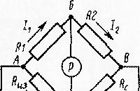
Figure 2 Diagram of the measuring bridge DC
readings of readings for both devices must be performed simultaneously by two persons at the command of one of them;
resistance should be measured at different current values;
when measuring higher accuracy, it is necessary to choose instruments of class not lower than 0.5.
To measure the resistance (10-8-10 + 16 ohms) to direct current with high accuracy are electrical bridges.
The measuring bridge, shown in Fig. 2, consists of three resistors R1, R2, Rc, which together with the measured resistance of the resistor Rm form a quadrangle ABCG. Its diagonal includes batteries GB and a galvanometer P (sensitive magnetoelectric device).
In fig. Fig. 3, a, b shows the general view and the scheme of the IWR reichord bridge. Bridges, in which the resistance in the shoulders is made in the form of a calibrated manganin wire, is called a reochord. Reohord is divided into two arms by sliding D on it. To measure the resistance Rk of the resistor Rx, it is enough to know the ratio of the resistances R1 / R2, therefore not the values of the resistances Ri and Rg are plotted on the sliding contact scale, but the values of their relations at different positions of the slider. The scale of the resistance switch in the comparison arm r3 is plotted from 0.1 up to 1000 ohms.
To determine the unknown resistance RH, it is connected to the clamps / and 2, first setting the estimated value of the unknown resistance in the comparison arm R3. Then press the button 5 (S) and rotate the handle of the reichord 3 until the arrow of the galvanometer is set to zero. Measured, the resistance is equal to the product of readings on a scale of a reichord 3 and the handle of a switch of 4 ranges of measurement.
IIM Bridge refers to resistance indicators and is intended for technical measurements of resistance. The power source of the indicator is a 3336 battery. When measuring resistances below i ohms, take into account the resistance of the connecting conductors.
For more accurate measurement of resistance in the practice of commissioning, DC bridges P 316, UMV, RZZZ are widely used.
A microhmmeter is used to measure low resistances, which gives an effect with a large number of measurements, for example: contact resistances of busbars, oil switches, resistances between adjacent pairs of collector plates of electrical machines and other electrical equipment. 
Fig. 3. Small-sized bridge - a- general view, b - scheme
When commissioning works using microhmmeters F415, F4104.
The insulation resistance of electrical circuits, machines and devices is the most important indicator of the state of an electrical installation.
This resistance is measured using a megohmmeter, given that its value largely depends on the time after which the countdown is made. Therefore, the measured value, which occurs 1 minute after the application of voltage, is taken as the measured insulation resistance. Measurements must be carried out in accordance with current safety regulations by persons with the required qualification group.
In assessing the state of the insulation resistance, the absorption method is used. This compares the readings of the megohmmeter obtained 15 and 60 s after the application of voltage to the insulation. As an indicator for comparison, take the ratio (coefficient of absorption)
Csa = R60 / R15,
where R60 and R15 are the insulation resistances measured after 60 and 15 s after applying voltage to the insulation.
The value of the absorption coefficient is compared with previous measurements. In the process of commissioning, measurements of this coefficient are performed at a positive temperature (not lower than 10 ° C). At 15-30 ° C for non-wetted windings, it is in the range of 1.3-2. Wetted windings have an absorption coefficient close to unity.
Before starting measurements, in order to avoid errors, the following measures should be taken: remove dust, clean insulators, eliminate dampness. Measurement is performed with a 1000 or 2500 megohm meter.
When performing adjustment works, megohm meters of various types and voltages are widely used (for 100, 500, 1000 and 2500 V). Diagrams of megohm meters are shown in fig. 4. The megohmmeter M4100 / 1-4 (Fig. 4, a) consists of a measuring mechanism P with a scale calibrated in ohms or megohms, a rectifier UD and a generator G of direct or alternating current with subsequent rectification, resistors Rl - R4 and capacitors Cl, C2. AC-to-DC conversion is necessary because when testing the readings of the devices would depend not only on the measured insulation resistance, but also on the capacitance of the circuit under test, this is especially true for cable and overhead lines with large capacitance.

Fig. 4. Schemes of megohm meters: a - M4100 / 1-4. 5 - M4100 / 5
The measuring mechanism is manufactured in the form of a two-frame magnetoelectric logometer. The measured resistance includes between the clamps L (line) and 3 (ground) and rotate the crank handle of the generator by hand. The current generated by the generator passes through two parallel branches. One part of the current flows from the rectifier UD through the resistance of resistors Rl, R2 and one of the windings of the measuring mechanism. The value of this current does not depend on the value of the measured resistance. Another part of the current flows through the second winding of the measuring mechanism, the measured insulation resistance and the resistance of resistors R3, R4. Consequently, the current value in this winding depends on the value of the measured resistance. Thus, the deviation of the measuring instrument arrow depends on the ratio of currents in its windings. Therefore, with a constant voltage developed by the generator, the deviation of the arrow of the measuring mechanism depends only on the value of the measured resistance, which allows putting Ohms directly on the scale (or megohms and kiloomas).
The generator anchor reaches the nominal frequency when the instrument handle is rotated at a frequency of 120 rpm. A centrifugal regulator is placed on the armature shaft, which ensures a constant voltage with increasing armature rotation frequency above the nominal one. In fig. 4, 6 shows the electric circuit of the M4100 / 5 megaohm meter at 2500 V, which differs in design from the M4100 / 1-4 megohmmeter by the number of capacitors and the rectifier assembled according to the voltage multiplication circuit.
Fig. 5. Measurements of insulation resistance measurement by megohm meters: a - M4100 / I-4 at the limit b - M4100 / 1 - 4 ka at the limit “ky”, c - M4 100/5 at the limit
"MJ", g - M4100 / 5 at the limit of "k"
To eliminate the effects of surface leakage currents, which can distort the measurement results of the insulation resistance, a special third terminal E (screen) is provided in the diagrams of some devices, which is connected directly to the output of the generator (Fig. 4.6). In this case, currents along the surface of the humidified insulator are diverted into the ground, bypassing the windings of the measuring mechanism. Line clamp L is protected by a protective insulating ring. Diagrams for measuring the insulation resistance with megohmmeters M4100 / 1-5 are shown in fig. 5, a - g. When measuring at the kQ limit, a jumper on one of the complete connecting wires is connected to terminals L - 3, and the measured resistance is between terminals 3 / she.
Technical characteristics of megohm meters M4100 / 1-5 are given in table. one.
Before measurements, you must ensure that the megohm meter is in good condition. When the generator knob is rotated, the indicator hand should be set to the “c” mark of the MOhm scale, and when the jumper between terminals L - 3 is set, to the “0” mark of the same scale. Otherwise, the device is considered defective.
Table I. Technical characteristics of megohm meters M 4100 / 1-5
Modification tion |
Limits |
The working part of the scale |
Nominal |
The main error,% of the length of the working scale |
||
Note. Technical indicators and megohm meters of the latest releases have minor changes.
It is forbidden to start measurements without being convinced that there is no voltage on the object under test!
Fig. 6. Scheme of inclusion of the megohmmeter M4I00 / 5
Depending on the measured resistance, the connection is made to the corresponding terminals, for example for megohm meters M 4100/5 as shown in Fig. 6
Measurements with a megohm meter are performed by two people: one rotates the handle of the generator, the other concerns the parts of the circuit to be measured. The countdown is made after the arrow takes a steady position.
When measuring insulation of high-voltage equipment, you should use a 2500 V megohmmeter, and when measuring low-voltage equipment, use 100, 500, and 1000 V.
When checking the insulation of electrical equipment, they take care not to apply increased voltage to parts and components of electrical installations with reduced test voltage (capacitors, rectifiers, microcircuits, etc.).
Page 14 of 14
Each phase of electrical wires, busbars, cables, windings and contacts of electrical devices must be carefully isolated from one another and from grounding structures. However, over time during the operation of electrical equipment, the dielectric characteristics of the insulation change. The aging of the insulation is affected by the temperature of the heating of the conductors and the outside air, the humidity of the room, switching overvoltages occurring in electrical circuits with inductive and capacitive elements, the duration of operation, etc. This insulation sometimes does not withstand even nominal voltages, resulting in electrical breakdown.
Therefore, in order for electrical equipment and devices not to fail due to the fact that the resistance of their insulation is below the permissible norm, and also that there are no short circuits due to electrical isolation breakdown in electrical networks, all its types are tested and tested in certain terms in accordance with the "Rules of technical operation of power plants and networks".
These tests are carried out, as a rule, during current and capital repairs of electrical equipment. In addition, turnaround, t, e. Preventive tests are carried out, which allow to identify defects arising in the process of installation or operation of equipment or cable lines, which makes it possible to eliminate these defects in a timely manner, prevent an accident or prevent a decrease in electricity output to consumers.
For each equipment, apparatuses and networks, there are standards for insulation resistance, which are established by the "Rules for Electrical Installations".
Two methods are used to determine the state of the insulation: measuring the resistance of a given section of an electrical installation or apparatus using a megohm meter or checking the state of the insulation with a high, strictly normalized voltage.
Fig. 46. Megohmmeter:
but - general form, b - simplified scheme: 1
- frame, 2
- inductor
When measuring the insulation resistance with a megohmmeter (Fig. 46), the arrow on its scale shows the insulation resistance of the apparatus under test or of a circuit. Framework 1
magnetoelectric systems are fed by current from the inductor 2
rotated by hand. When clamps X1 and X2 open, the current passes only through the frame with an additional resistor R2 and the moving part of the magnetoelectric system is installed in one of its extreme positions with a sign, which means infinitely large resistance. If you close the clamps X1 and X2, the current will go through the second frame with an additional resistor R1. In this case, the mobile system will be installed in another extreme position marked on the scale “0”, i.e. the measured resistance will be equal to zero. When connecting the measured resistance Rx to clamps X1 and X2 The moving system will be set to an intermediate position between and 0 and the arrow on the scale will indicate the value of this resistance. The scale of the megohmmeter is graduated in kilohms and megohms: 1 kΩ = 1000 Ohm; 1 MΩ = 1000 kΩ. As a source of direct current in mega-megrags, inductor direct-current generators with manual drive from the handle are used.
The voltage at the external terminals of the generator depends on the frequency of rotation of the handle. For smoothing oscillations during rotation, a centrifugal regulator is mounted in the drive.
The nominal frequency of rotation of the generator megohmmeter is 2 rev / s or 120 rev / min.
To connect the megohmmeter, use PVL connecting wires with moisture-proof insulation, otherwise the readings of the megohmmeter can be significantly distorted.
Megohm meters are available with a rated voltage at the terminals: Ml 101M - 500 and 1000 V, MS-05 - 2500 V.
When measuring the insulation resistance of long cable lines and windings of electrical machines and transformers, the reading of the megohmmeter at the beginning of the rotation of the handle decreases sharply. This is due to the presence of significant capacity in cable lines and electric machines through which the charge current passes. Therefore, in such cases, when using a megohm meter to measure the insulation resistance, the readings of the device are counted only after 60 s. since the start of rotation of the handle.
Touching the measured circuit during rotation of the handle connected to the megohmmeter circuit is dangerous and can lead to electric shock. Therefore, the measurements take the necessary security measures that exclude the possibility of people touching the electrical circuits.
In large capacity installations (long cable lines, high power transformers), the circuit to be measured may acquire a significant electrical charge. Therefore, after removing the voltage from the megohmmeter, such circuits are discharged by means of a flexible copper wire to the ground, using an insulating rod to connect to each of its phases. In installations with voltages above 1000 V, the discharge of cables and large machines is performed in dielectric gloves and galoshes.
For testing high voltage insulation using a variety of devices rectified and alternating current.
Most often, when testing insulation, a kenotron installation is used, the schematic diagram of which is shown in fig. 47, a. It is mounted in the back of a car and has its own source of electricity. The positive pole of the kenotron lamp (anode) is grounded, and the negative pole (cathode) is connected to one of the phases of the electrical installation under test (for example, a cable), while the other two phases and the shell are grounded (Fig. 47b).
The kenotron isolation tester KII-70 is an installation consisting of a mobile control panel and a kenotron attachment. It is intended for testing solid liquid dielectrics with direct voltage up to 70 kV. The test voltage is changed from 0 to 70 kV using a regulator with an additional winding to power the signal lamp circuit.
The kenotron attachment consists of a transformer and a kenotron placed in a bakelite cylinder filled with transformer oil. In the upper part of the console, there is a three-limit micro-ammeter with a scale of 200, 1000 and 5000 μA and a limit switch for measuring leakage currents. The attachment has pins for connecting high voltage DC circuits and the test object. In addition, the device is equipped with a device of overcurrent protection with two settings: coarse and sensitive. 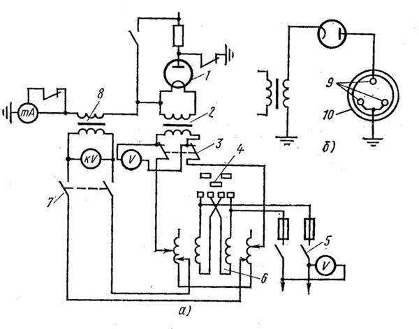
Fig. 47. Schemes kenotronic installation:
but - principled b - Lead cable tests; 1
- kenotronnaya lamp, 2
- transformer heat, 3
- the switch of heat, 4
- power switch, 5
- power switch, 6
- control transformer, 7
- contactor, 8
- test transformer, 9
- cable cores 10
- cable sheath
on the side of the higher voltage tester, while it does not work in minute power mode at a voltage of 50 kV.
Sensitive setpoint shuts down the device when a short circuit occurs on the high voltage side of the transformer. In this case, the protection should not operate at a voltage of 70 kV and a secondary current of 5 mA.
On the cover of the tester's control panel there is a device for overcurrent protection, a switch for maximum protection, an alarm lamp, and a kilovoltmeter.
For a direct current test, a kenotron attachment is installed on the hinged door of the control panel and the test object is connected to it. Using the regulator, the voltage is applied to the control panel, gradually increasing it to the test value. Voltage is monitored on a scale calibrated in kilovolts (maximum). At the last minute of the test time, a leakage current is measured using a microammeter.
The test with alternating current of industrial frequency is performed by connecting the test object to the AC output, after which the voltage is raised by the regulator to the test one. Voltage control is carried out on a kilovoltmeter scale, calibrated in kilovolts.
The stress during the tests is smoothly raised to the test and maintained unchanged during the entire test period. The test time is determined by the “Rules of technical operation of electrical installations of consumers and safety regulations for the operation of electrical installations of consumers” for each type of equipment, devices and networks and ranges from 1 to 10 minutes.
During the overhaul of distribution devices with voltage up to 1 kV, which is held once every 3 years, the insulation resistance of the elements of the actuators of switches, disconnectors, secondary circuits of equipment, power and lighting wiring is tested with a power frequency of 1 kV for 1 min or 1000 V megohm When measuring insulation resistance in power circuits, electrical receivers, devices and devices should be disconnected, and in lighting networks - lamps should be turned out, plug sockets should be disconnected yuchateli, group shields of power consumers.
The smallest allowable insulation resistance values of the secondary control circuits, protection, signaling of relay-contact circuits, power and lighting electrical wiring, switchgear, switchboards and conductors with voltage up to 1000 V are 0.5 MΩ, and the operating current and voltage busbars on the control panel are 10 MΩ
With an increased voltage of 1000 V for 1 min, secondary circuits of protection, control, and alarm systems are tested with all attached devices (coils of drives, automatic machines, magnetic starters, contactors, relays, etc.). The insulation resistance of the battery after its installation should not be less than:
Measurement of loads and voltages at the control points of the lighting network is performed once a year; insulation resistance of portable transformers with a secondary voltage of 12–42 V is tested once every 3 months, and stationary ones once a year.
Switches, disconnectors, grounding knives, shorting switches, separators and their drives are tested at least once every 3 years simultaneously with major repairs. The smallest permissible values of the resistance of the reference insulation, measured by a megohm meter at a voltage of 2.5 kV, with a rated voltage of up to 15 kV are 1000 MΩ and over 20 kV - 5000 MΩ. Testing of this insulation of switches up to 35 kV with increased voltage of industrial frequency is carried out within 1 min. At the same time, the resistance of contacts to direct current is measured, which is: for VMG-133 (1000 A) - 75 µOhm; VMP-10 (1000 A) - 40 µOhm; VMP-10 (1500 A) - S0 mΩ; VMP-10 (600 A) - 55 µOhm.
The insulation resistance of suspended and multi-element insulators is measured with a 2.5 kV megohm meter only at positive ambient temperatures, and the insulation resistance of each suspension insulator or pin insulator element must be at least 300 MΩ.
The test with increased voltage of industrial frequency of newly installed supporting multi-element and suspension insulators is carried out with a voltage of 50 kV. Each element of the ceramic insulator is tested for 1 minute, from organic material - 5 minutes. Support single-element insulators of internal and external installations are tested with increased voltage, indicated in Table. 24, for 1 min.
Table 4. Test voltage of single-element reference insulators, kV
Pin insulators for busbars with a voltage of 6–10 kV, supporting and suspended porcelain dish-shaped insulators, as well as contact connections for tires and equipment connections without thermal indicators, are tested once every 3 years. The insulation resistance test of bushings and bushing insulators is tested with a megohmmeter at a voltage of 1000–2500 V for bushings with paper-oil insulation. Insulation resistance must be at least 1000 MΩ. Insulators of inputs and through passage with a voltage up to 35 kV are tested by the increased tension which size is specified in tab. five.
Measurement of insulation resistance of moving and guiding parts made of organic materials, oil switches of all voltage classes is produced by a megohmmeter at a voltage of 2500 V. Moreover, the smallest permissible insulation resistance must be at least: for voltages up to 10 kV - 1000 MOhm, from 15 to 150 kV - 3000 MΩ
Table 5. Test voltage of the bushings and bushing insulators
Insulation testing of oil circuit breakers with voltage up to 35 kV with increased voltage of industrial frequency is performed for 1 min. Test voltage is taken in accordance with the data table. 6
Table 6. Test voltage of external insulation of oil circuit breakers
Resistance to direct current of the contacts of the oil switches should not differ from the data of the manufacturer.
When testing oil circuit breakers, its speed and temporal characteristics are also checked. These measurements are made for switches of all voltage classes. Measured characteristics should be in accordance with the manufacturer's data.
After the repair, the insulation of the windings of the power transformers together with the inputs is subjected to tests with increased AC voltage at an industrial frequency of 50 Hz. The test voltage depends on the type of repair and scope of work (with or without a change in transformer windings).
The insulation of each winding, not electrically connected to another, is tested separately.
The values of the test voltage at an industrial frequency of 50 Hz are shown in Table. 7
Table 7. Test voltage of the insulation of the windings together with the inputs, kV
The test results are recorded. These data are necessary for comparing the results obtained with the results of previous tests conducted at different times prior to this repair.
Tests of transformers after repair are performed throughout the program and in the amount stipulated by the current rules and regulations.
During preventive tests, the insulation of the windings of power transformers is tested with a higher voltage of industrial frequency in accordance with the table. 8 for 1 min.
Table 8. Test voltages of the internal insulation of oil-filled transformers
The resistance of the windings to direct current is measured on all branches and may differ by no more than 2% from the manufacturer's data.
The transformer transformer ratio check is performed at all switching steps. Tolerances can be no more than 2% of the values obtained on the same branch in other phases, or from the data of the manufacturer.
The minimum breakdown voltage of oil, determined in a standard vessel before pouring into transformers and insulators, for voltage up to 15 kV should be 30 kV, and from 15 to 35 kV - 35 kV.
For fresh oil, before pouring the newly commissioned transformer, a complete chemical analysis is performed according to a special program.
Measurement of insulation resistance of tugs and leads made of organic materials is made by a megohmmeter at a voltage of 2500 V. The lowest permissible insulation resistance made of organic materials at a nominal voltage up to 10 kV should be 1000 MΩ, at a voltage from 15 to 150 kV - 3000 MΩ.
The insulation resistance of the primary windings of measuring transformers is measured with a megohmmeter for a voltage of 2500 V, and the secondary windings for a voltage of 500 or 1000 V. The insulation resistance of the primary winding is not normalized, and the resistance of the secondary winding together with the circuits connected to it must be at least 1 MΩ.
Depending on the insulation resistance of the primary windings of current transformers and voltages up to 35 kV, the test is performed at the following test voltage values. If the insulation resistance is calculated for a voltage of 6 kV, the test voltage is assumed to be 28.8 kV, for a voltage of 10 kV - 37.8 kV, for a voltage of 20 kV - 58.5 kV.
The duration of application of the test voltage for the primary windings of instrument transformers is 1 min. Only for current transformers with insulation from solid ceramic materials or cable masses the duration of application of the test voltage is 5 minutes.
In dry reactors, the insulation resistance of the windings relative to the mounting bolts is measured by a megohm meter for a voltage of 1000 - 2500 V. Its value should be at least 0.5 MΩ.
Porcelain insulation of the reactor, as well as fuses above 1000 V, is tested at a high voltage of industrial frequency for 1 min with the following test voltage values: at a rated voltage of 6 kV - 32 kV, at 10 kV - 42 kV, at 20 kV - 65 kV.
Insulation resistance of power cable lines is measured with a megohmmeter at a voltage of 2500 V. In fig. 48 is a diagram of switching on a megohmmeter when measuring cable resistance. For power cable lines up to 1000 V, the insulation resistance must be at least 0.5 MΩ, and at voltages above 1000 V, the insulation resistance is not normalized. Measurements with a megohmmeter should be made before and after testing the cable with an increased voltage. Power cables with voltages higher than 1000 V are tested with increased voltage of the rectified current.
Test stresses and the duration of their application are given in Table. 9.
The data of all tests and measurements are recorded in the electrical equipment test log and in the test and measurement reports.
Table 9. Test voltage of rectified current for power cables
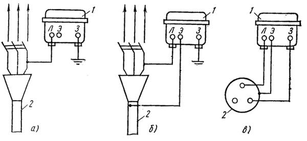
Fig. 48. Wiring diagram of the megohmmeter when measuring cable resistance
but - a circuit for measuring insulation relative to earth, b - scheme in the presence of surface leakage currents, at - insulation measurement between the conductors, 1 2 - cable
These data are used for comparison in subsequent tests and measurements. They provide an opportunity to analyze the condition and performance of the equipment, schedule the time for the necessary repairs to increase insulation resistance or reduce leakage currents and thus increase the equipment operation time in trouble-free mode.
Electrical equipment is regularly tested.which pursue the objectives of verifying compliance with established specifications, obtaining data for the following preventive tests, establishing the absence of defects, and also to study the operation of electrical equipment. There are the following types of tests: operational, acceptance, control, typical, special.
Type tests are used for new equipment, which differs from old samples with an updated design, device. This type of test is carried out by the manufacturer in order to verify compliance with all requirements and standards that apply to this type of equipment or technical conditions.
To verify the compliance of the manufactured product with all the main technical specifications, each product is subjected to control tests (apparatus, machine, instrument, etc.). For the control tests, as a rule, an abbreviated program of work is used (as compared with the standard ones).
Acceptance tests used after the installation of the newly commissioned equipment in order to assess its suitability for use.
Performance tests are held for equipment in operation, including those that are out of repair. This type of test is used to determine the health of the equipment. To operational include tests for current, capital repairs, as well as preventive tests that are not related to the withdrawal of equipment for repair.
For research purposes or other special programs may be carried out special tests.
Some of the test work is done similarly for almost all elements of electrical equipment. These types of work include: testing and testing of insulation, control of electrical connections.
When checking electrical connections, the following actions are taken:
1) acquaintance with the technical information on the object - installation and principal (full) switching circuits, cable magazine are studied;
2) checking for compliance with the design of real equipment and equipment;
3) checking and inspecting the compliance of cables and wires (section, material, brand, etc.) with the current rules and design;
4) control of the correctness and availability of marking on the conductors of cables and wires, the terminals of devices, terminal blocks;
5) quality control of installation (cabling, laying of cables on panels, reliability of contact connections, etc.);
6) continuity (control of correct installation of the circuits);
7) test the reliability of electrical circuits when applying.
The most complete tests in the circuits of primary and secondary switching are carried out during the acceptance tests after the completion of the installation of electrical equipment. During preventive tests, the number of switching control operations is significantly reduced. Installers or service technicians should correct any deviations from the project or installation errors that were found during the test. In order to change or retreat from the project, you must first obtain the consent of the project organization. Any such changes are required to provide in the form of drawings.

As you know, electrical voltage should have its own measure, which initially corresponds to the value that ...

Coal is the first fossil fuel that man began to use. Currently as an energy carrier ...

Thermal relays are electrical devices whose main purpose is to protect the engine against excessive ...

Work plan: Introduction Structure of the carbon atom. Dissemination in nature. Carbon production. Physical and chemical ...

Electrical quantity, which characterizes the property of the material to prevent the flow of electric current. AT...
Ampere's law is one of the most important and most useful laws in electrical engineering, without which scientific and technical ...
The technological scheme of a nuclear power plant depends on the type of reactor, the type of coolant and moderator, as well as a number of other ...

Usually, negative decimal numbers are automatically converted to reverse or ...
Informatics and ICT Grade 8 Workbook Bosova LL 2012 Answers, Informatics and ICT Grade 8 Workbook ...
Light / Electricity meters and meteringSeptember 1 Mosenergosbyt requires data transfer every month ...
With the advent of technical means of storing and transmitting information, new ideas and coding techniques emerged ....
C (carboneum), non-metal chemical element of group IVA (C, Si, Ge, Sn, Pb) of the periodic system ...

Exhaustion of hydrocarbon fuels, environmental degradation and a number of other reasons sooner or later ...
First of all, let us dwell on the basic and general question for the problems under consideration: find out what depends on ...

Anthracite (Greek. Ανθραξ - coal), Solid, high density, shiny coal containing more than 90% carbon ...
Electrical equipment is regularly subjected to tests that pursue the objectives of checking compliance ...